Introduction:
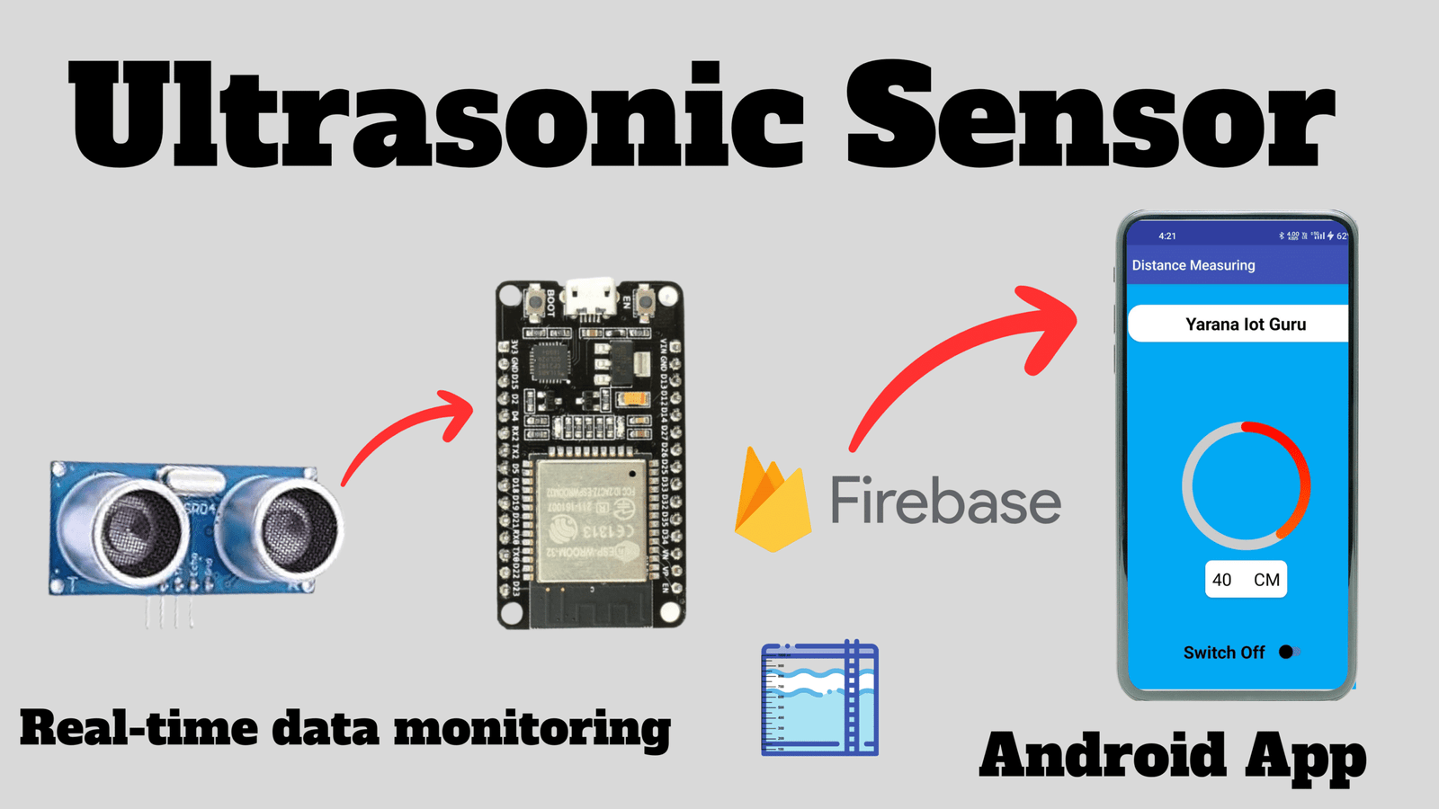
Whether you’re a tech enthusiast, hobbyist, or delving into the realms of IoT, our project offers a fascinating journey into the convergence of hardware and software. In a world driven by innovation, the Smart Distance Measuring System stands as a testament to how technology can address real-world challenges.
Why Smart Distance Measuring?
In the era of boundless innovation, intelligent and efficient solutions are in high demand. Our system exemplifies how technology can seamlessly measure distances with wireless connectivity and cloud integration, providing a sophisticated and convenient solution.
Key Components: ESP32, Ultrasonic Sensor, Firebase
- ESP32: The versatile microcontroller at the core of our project, known for handling IoT applications.
- Ultrasonic Sensor: The eyes of our project, utilizing sound waves for precise distance measurements.
- Firebase: A robust cloud platform facilitating seamless data storage and retrieval, allowing global monitoring and control.
What Sets This Project Apart?
This project goes beyond assembling components; it’s an exploration of communication and collaboration. Gain insights into IoT coding, real-time data handling, and creating tangible solutions.
Ready for the adventure? Let’s turn this concept into reality with our step-by-step guide!
Step 1: Gather Your Components
Ensure you have the necessary components: ESP32 Microcontroller, Ultrasonic Sensor, Firebase Account, Breadboard, Jumper Wires, LED, and Resistor.
Step 2: Set Up Your Workspace
Create an organized workspace with ample lighting. A clutter-free environment streamlines the building process.
Step 3: Connect the Ultrasonic Sensor to ESP32
- VCC to 5V on ESP32.
- GND to GND on ESP32.
- TRIG to TRIG_PIN (pin 12 in code).
- ECHO to ECHO_PIN (pin 14 in code).
Step 4: Set Up Firebase
Create a Firebase project.


Set up a Realtime Database.


Copy Your Project Url & Api Key :


Step 5: Install Required Libraries

Install WiFi.h and IOXhop_FirebaseESP32 libraries in Arduino IDE.
Step 6: Code Your ESP32
Click Here To Download Code & Android APP.
Step 7: Connect LED to ESP32 (Optional)
- Anode (+) to pin 2 on ESP32.
- Cathode (-) to GND on ESP32 through a resistor.
Step 8: Upload Code to ESP32

Connect ESP32, select board and port, and upload code in Arduino IDE
Step 9: Power Up and Test
Power up ESP32, open Serial Monitor to monitor distance readings, and check for errors.
Step 10: Explore Firebase Integration
Visit Firebase Realtime Database dashboard to view distance data. Experiment by changing LED status in the database for real-time changes.
Step 11-15: Further Enhancements, Documentation, Sharing, and Staying Updated.
Stay tuned for additional links to GitHub, code downloads, app downloads, and the YouTube video for a comprehensive guide!


