Introduction:
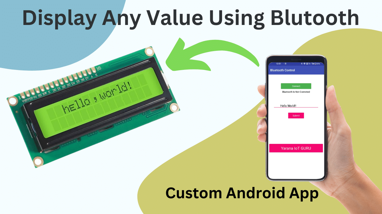
The 16×2 LCD display is an indispensable component in IoT projects, offering a convenient way to display information. In this comprehensive tutorial, we will explore how to print text on a 16×2 LCD using a dedicated app. This guide is tailored for beginners and enthusiasts, providing a clear understanding of hardware setup, pin configuration, software installation, and code execution.
Hardware Setup:
Begin by explaining the essential hardware components needed for this project, including:
- 16×2 LCD module
- Jumper wires
- Breadboard (if used)
- Power source (e.g., Arduino or Raspberry Pi)
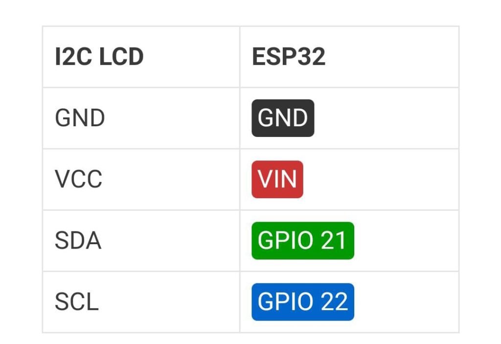
Provide a detailed step-by-step guide on how to connect the LCD module to your chosen microcontroller (e.g., Arduino), including pin configurations for data (D4-D7), control (RS, RW, EN), and power (VCC, GND).
Software Configuration:
Describe the software required for this project and guide readers through the installation process. Highlight the following software aspects:
- Installation of the LCD control app on a computer or microcontroller (if applicable).
- Configuration settings within the app, such as COM port selection (if using a microcontroller like Arduino).
Pin Configuration:
Dedicate a section to explain the significance and role of each pin on the 16×2 LCD module. This includes details on the following pins:
- Data pins (D4-D7): Explain how data is transmitted from the microcontroller to the LCD.
- Control pins (RS, RW, EN): Describe the purpose of each control pin and their role in managing data flow.
- Power pins (VCC, GND): Highlight the voltage and ground connections for the LCD module.
Certainly, let’s add a section to your article that explains how to connect jumper wires to the 16×2 LCD module and which pins they should be connected to:
Connecting Jumper Wires to the 16×2 LCD Module:
To successfully interface your 16×2 LCD module with a microcontroller, you’ll need to connect jumper wires from the microcontroller to the LCD module. Here’s a step-by-step guide on how to do it:
- Data Pins (D4-D7): These pins are used for transferring data from the microcontroller to the LCD module. Connect them as follows:
- Connect D4 on the LCD module to a digital pin on your microcontroller (e.g., Arduino).
- Connect D5 on the LCD module to another digital pin on your microcontroller.
- Likewise, connect D6 on the LCD module to a digital pin.
- Lastly, connect D7 on the LCD module to a digital pin.
- Control Pins (RS, RW, EN): These pins are essential for controlling the LCD’s operation. Here’s how to connect them:
- Connect RS (Register Select) on the LCD module to a digital pin on your microcontroller. This pin controls whether data sent to the LCD is treated as a command or text.
- Connect RW (Read/Write) on the LCD module to ground (GND) if you are only writing data to the LCD (common practice for most applications). Alternatively, you can connect it to another digital pin if you intend to read data from the LCD.
- Connect EN (Enable) on the LCD module to another digital pin. This pin is used to enable the LCD to read data.
- Power Pins (VCC, GND): Properly supplying power is crucial for the LCD’s functionality. Connect them as follows:
- Connect VCC (Voltage Common Collector) on the LCD module to the 5V output on your microcontroller (e.g., Arduino).
- Connect GND (Ground) on the LCD module to the ground (GND) output on your microcontroller.
Ensure that your connections are secure, and double-check them against your microcontroller’s pinout and the LCD module’s pin configuration. Using jumper wires makes it easy to adjust connections and troubleshoot any issues that may arise during your project.

Code Example:
Provide a comprehensive code example that demonstrates how to print text on the 16×2 LCD using the software/app introduced earlier. Include comments in the code to explain each section’s functionality. Help readers understand how to customize the code for their specific needs.
| #include <Wire.h> #include <LiquidCrystal_I2C.h> #include <BluetoothSerial.h> BluetoothSerial ESP_BT; // Bluetooth object LiquidCrystal_I2C lcd(0x27, 16, 2); // I2C address 0x27 for a 16×2 LCD display void setup() { Serial.begin(115200); // Initialize Serial Monitor lcd.init(); // Initialize the LCD lcd.backlight(); lcd.setCursor(0, 0); ESP_BT.begin(“ESP32_BLUETOOTH”); // Bluetooth device name Serial.println(“Bluetooth Device is Ready to Pair”); lcd.print(“BT is Ready”); } void loop() { if (ESP_BT.available()) { String text = ESP_BT.readString(); lcd.setCursor(0, 0); lcd.clear(); lcd.print(text); Serial.println(“Received Value: ” + text); } } |
Conclusion:
Summarize the key takeaways from the tutorial. Emphasize the importance of understanding pin configurations, hardware setup, and software integration when working with 16×2 LCD displays in IoT projects. Encourage readers to explore further projects and applications.
