Welcome to YaranaIoT Guru, your trusted platform for exploring advanced IoT innovations, embedded systems, and real-world connectivity solutions.
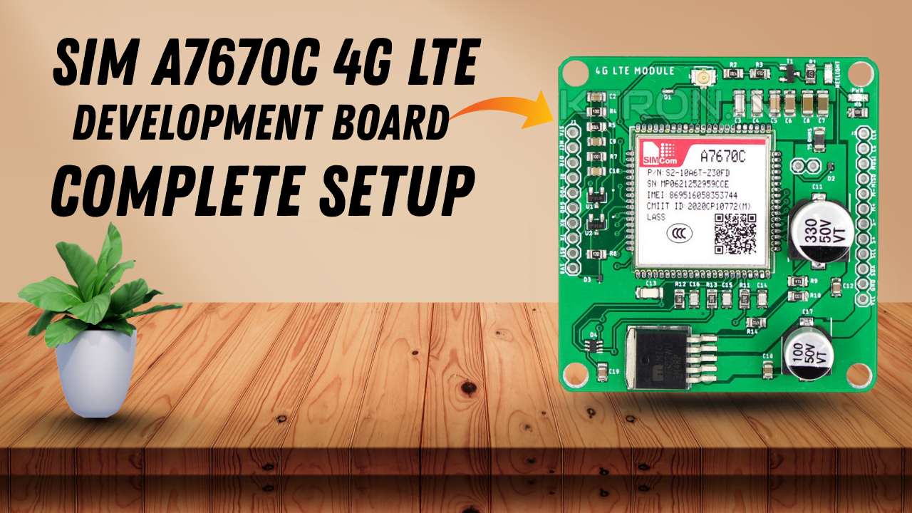
In this post, we’ll dive deep into one of the most powerful and feature-rich communication modules in the IoT industry — the SIM A7670C 4G LTE Development Board.
This tutorial will cover everything — from basic setup, pin configuration, AT commands, and real-world testing — to help you integrate this board with microcontrollers like ESP32, Arduino, and Raspberry Pi for IoT, GPS, and cloud-based applications.
🔹 What is the SIM A7670C 4G LTE Module?
The SIM A7670C is a 4G LTE communication module manufactured by SIMCom, part of their A76XX series. It supports LTE CAT-1, GSM, and GPRS connectivity, making it a high-performance choice for IoT applications requiring stable and fast cellular data.
The module integrates 4G LTE, SMS, Voice Call, and GPS (in certain versions) — allowing developers to create smart IoT systems that can communicate globally without Wi-Fi.
This module is ideal for applications such as:
- Remote data logging
- Smart metering
- Industrial automation
- GPS-based tracking
- Home and agricultural monitoring
🔹 Why Use the A7670C Instead of SIM800L or SIM900A?
Older GSM modules like SIM800L or SIM900A only support 2G networks. As many regions are phasing out 2G, developers need a future-proof 4G LTE solution — and that’s exactly where the A7670C shines.
| Feature | SIM800L | SIM900A | A7670C |
|---|---|---|---|
| Network | 2G GSM | 2G GSM | 4G LTE CAT-1 |
| Internet | GPRS | GPRS | LTE (Up to 10 Mbps) |
| GPS | No | No | Optional |
| AT Commands | Basic | Basic | Advanced |
| Power | 3.7–4.2V | 3.7–4.2V | 5V (Stable) |
| Compatibility | Arduino, ESP32 | Arduino | Arduino, ESP32, Raspberry Pi |
Thus, the A7670C not only ensures high-speed data transmission but also supports VoLTE, SMS, HTTP, HTTPS, and MQTT protocols.
🔹 Key Features of SIM A7670C
✅ LTE CAT-1, GSM, and GPRS connectivity
✅ Compatible with 4G/3G/2G networks
✅ Supports voice calls, SMS, and TCP/IP stack
✅ GPS and GNSS support (depends on version)
✅ Built-in USB and UART interfaces
✅ AT Command controlled (same as SIMCOM series)
✅ Low power consumption and wide voltage input
✅ Supports HTTP, HTTPS, FTP, and MQTT protocols
✅ Ideal for IoT, Smart Metering, and GPS projects
🔹 Package Includes
- SIM A7670C Development Board
- LTE Antenna
- GSM Antenna
- GPS Antenna (optional)
- USB Cable (for PC connection)
- Jumper wires and headers
💡 Understanding LTE CAT-1
CAT-1 is a type of LTE designed specifically for IoT devices. It provides moderate data speed (up to 10 Mbps) with low power consumption, perfect for smart applications that don’t need video streaming but require stable internet — such as sensor data uploads, MQTT communication, and GPS tracking.
🎥 Watch Full Setup Video on YaranaIoT Guru YouTube Channel
Learn how to connect the A7670C module with ESP32 and send HTTP requests over 4G LTE.
⚙️ Understanding the Hardware
The SIM A7670C Development Board is designed to simplify the integration of the LTE module into IoT projects. It includes a SIM slot, power management IC, UART interface, USB communication, and status indicators — all on a single PCB.
This makes it beginner-friendly yet powerful enough for professional IoT applications.
Let’s explore the hardware step by step 👇
🔹 A7670C Module Layout Overview
When you look at the A7670C board, you’ll notice the following key sections:
| Section | Description |
|---|---|
| SIM Slot | Insert a 4G-compatible SIM card (Nano or Micro depending on board version). |
| Main Chip (A7670C) | The LTE modem chip responsible for handling cellular communication. |
| Antenna Connectors | One for LTE, one for GSM, and one for GPS (if available). |
| UART Interface (TX, RX, GND, VCC) | Connects to ESP32, Arduino, or USB-TTL converter for AT commands. |
| USB Port (Micro/Type-C) | Used for firmware updates or direct PC communication. |
| Power Input (VIN / 5V) | For stable 5V power supply to the board. |
| LED Indicators | Power status, network connection, and data transmission indicators. |
🔹 Voltage and Power Requirements
The A7670C requires a stable 5V power source capable of supplying at least 2A current during data transmission bursts.
If your power supply is weak or unstable, the module will restart or disconnect from the network.
💡 Tip:
If you’re powering the board from a microcontroller like ESP32 or Arduino, do not draw power directly from their 5V pin — use a separate 5V 2A adapter or DC power module instead.
🔹 Recommended Power Circuit
A stable circuit for the A7670C power supply:
5V Adapter (2A) → DC Jack → Capacitor (470µF) → A7670C VIN
This capacitor helps smooth out voltage drops during 4G transmission spikes.
🔹 Pin Configuration (UART Interface)
| Pin | Function | Description |
|---|---|---|
| VCC (5V) | Power input | Connect 5V regulated supply |
| GND | Ground | Common ground with microcontroller |
| TXD | Transmit Data | Sends data from module to MCU |
| RXD | Receive Data | Receives data from MCU |
| RST | Reset | Optional manual reset pin |
| PWRKEY | Power control | Used to power ON/OFF the module |
| DTR | Sleep/Wake control | Used for low-power mode |
| RI | Ring Indicator | Used for call/SMS notifications |
🔹 Connecting A7670C with ESP32
Here’s a typical connection setup between ESP32 and SIM A7670C:
| A7670C Pin | ESP32 Pin |
|---|---|
| TXD | GPIO16 (RX2) |
| RXD | GPIO17 (TX2) |
| GND | GND |
| VCC | 5V (External Power) |
| PWRKEY | GPIO4 (optional control) |
📌 Note:
Make sure you use Serial2 of ESP32 (Serial2.begin(115200, SERIAL_8N1, 16, 17);) for communication.
The baud rate can be adjusted using an AT command later.
🔹 Connecting A7670C with Arduino UNO
Since Arduino UNO runs at 5V logic, it’s directly compatible with the A7670C UART pins.
However, ensure a strong external 5V 2A supply for the module.
| A7670C Pin | Arduino UNO Pin |
|---|---|
| TXD | Pin 2 (SoftwareSerial RX) |
| RXD | Pin 3 (SoftwareSerial TX) |
| GND | GND |
| VCC | External 5V |
| PWRKEY | Pin 7 (optional) |
You’ll use the SoftwareSerial library on Arduino for this communication.
🔹 Powering ON the Module
To power ON the A7670C module:
- Connect the PWRKEY pin to GND for 1 second, then release it.
- The NETLIGHT LED will start blinking — this means the module is powered.
- Fast blinking: Searching for network
- Slow blinking: Registered successfully
🔹 Testing Connectivity via USB
If you connect the A7670C board to your computer via the USB port, it will appear as multiple COM ports (e.g., Modem, Diagnostics, AT interface).
You can open AT Command mode using a serial terminal (like PuTTY or TeraTerm) and test the module manually.
Default baud rate: 115200 bps
💬 Basic Power Verification Steps
Once everything is connected:
- Check the Power LED → Should be ON.
- Observe the Network LED → Should blink slowly (indicates 4G registered).
- Open Serial Monitor → Send command
AT→ Expect responseOK.
If all these are correct, your hardware setup is successful ✅
🛰️ Understanding AT Commands
AT commands (short for Attention Commands) are the communication language used to control GSM/LTE modules like the SIM A7670C.
They allow you to:
- Test connectivity
- Send and receive SMS
- Manage calls
- Configure network and APN
- Connect to the Internet
- Perform HTTP, MQTT, or TCP/UDP requests
When connected via USB or UART, you can type AT commands directly in your Serial Monitor or send them programmatically via Arduino/ESP32.
🧠 Before You Begin
✅ Make sure your SIM card has:
- Active 4G data plan
- No SIM PIN lock
- Good network coverage
✅ Required tools:
- Arduino IDE or ESP32 IDE
- Serial Terminal Software (e.g., PuTTY, CoolTerm, or AT Command Tester)
⚡ Basic AT Command Testing
Once your A7670C board is connected (via USB or UART), open the Serial Monitor at 115200 baud rate and type the following commands.
| Command | Description | Expected Response |
|---|---|---|
AT | Test communication | OK |
ATI | Display module information | Module name, firmware version |
AT+CPIN? | Check SIM card status | READY |
AT+CSQ | Signal quality | e.g., +CSQ: 20,99 (higher is better) |
AT+CREG? | Network registration | +CREG: 0,1 = Registered |
AT+COPS? | Show current network operator | e.g., Jio, Airtel, VI |
AT+CGATT? | Check GPRS attach status | +CGATT: 1 (attached) |
💡 If you get ERROR or no response, ensure:
- SIM is inserted correctly
- Power supply is stable
- Baud rate is correct (default: 115200)
🌐 Setting Up Mobile Internet (APN Configuration)
Every telecom operator uses a specific APN (Access Point Name) for 4G data access.
| Network | APN |
|---|---|
| Jio | jionet |
| Airtel | airtelgprs.com |
| VI (Vodafone Idea) | internet |
| BSNL | bsnlnet |
Use the following commands to configure your APN:
AT+CGDCONT=1,"IP","jionet"
AT+CGACT=1,1
AT+CGATT=1
Now test the network connection:
AT+CGPADDR
✅ If successful, it will return your IP address, meaning the module is connected to the internet.
🌍 Testing HTTP Requests
Once internet access is confirmed, you can test HTTP connections (GET and POST requests) to check data transfer.
🔸 Example 1: HTTP GET Request
AT+HTTPINIT
AT+HTTPPARA="CID",1
AT+HTTPPARA="URL","http://example.com/test"
AT+HTTPACTION=0
AT+HTTPREAD
AT+HTTPTERM
Explanation:
HTTPINIT→ Initializes HTTP serviceHTTPPARA→ Sets parameters like URL and connection IDHTTPACTION=0→ Executes HTTP GETHTTPREAD→ Reads the responseHTTPTERM→ Closes the HTTP session
If everything is fine, you’ll get an HTTP response like:
+HTTPACTION: 0,200,45
Here 200 = Success, and 45 = bytes received.
🔸 Example 2: HTTP POST Request
AT+HTTPINIT
AT+HTTPPARA="CID",1
AT+HTTPPARA="URL","http://api.thingspeak.com/update"
AT+HTTPPARA="CONTENT","application/x-www-form-urlencoded"
AT+HTTPDATA=50,10000
api_key=YOURKEY&field1=25.5
AT+HTTPACTION=1
AT+HTTPREAD
AT+HTTPTERM
This command uploads sensor data (e.g., temperature = 25.5) to a web server such as ThingSpeak or Ubidots.
⚙️ Using AT Commands via Arduino
You can also control the module directly through an Arduino or ESP32 sketch.
Here’s an example code snippet:
#include <HardwareSerial.h>

HardwareSerial LTE(2); // Using UART2 on ESP32

void setup() {
  Serial.begin(115200);
  LTE.begin(115200, SERIAL_8N1, 16, 17); // RX2, TX2 pins
  delay(2000);
  Serial.println("Initializing A7670C...");
  LTE.println("AT");
}

void loop() {
  while (LTE.available()) {
    Serial.write(LTE.read());
  }

  if (Serial.available()) {
    LTE.write(Serial.read());
  }
}
➡️ Open Serial Monitor, select “Both NL & CR,” and type AT commands directly through ESP32.
This lets you send any AT command from the Arduino IDE without external terminal software.
🔍 Checking Network Type
You can verify whether the module is on 2G, 3G, or 4G with:
AT+COPS?
AT+CNMP?
AT+CMNB?
AT+CNMP=38→ LTE OnlyAT+CNMP=13→ GSM OnlyAT+CNMP=2→ Auto Mode
To switch to 4G LTE only mode:
AT+CNMP=38
AT+CMNB=1
This ensures stable high-speed connectivity for IoT applications.
🧩 Testing with Ubidots or Thingspeak
You can send live IoT data using simple HTTP commands.
For example, to upload temperature and humidity:
AT+HTTPINIT
AT+HTTPPARA="CID",1
AT+HTTPPARA="URL","http://industrial.api.ubidots.com/api/v1.6/devices/esp32"
AT+HTTPPARA="CONTENT","application/json"
AT+HTTPDATA=60,10000
{"temperature":25.5,"humidity":80,"token":"YOUR_UBIDOTS_TOKEN"}
AT+HTTPACTION=1
AT+HTTPREAD
AT+HTTPTERM
✅ If response +HTTPACTION:1,200,x → Success
✅ If +HTTPACTION:1,603 → Server error (check URL or token)
📡 SMS and Call Commands (Optional)
You can also send SMS or make calls for alerts.
Send SMS:
AT+CMGF=1
AT+CMGS="+91xxxxxxxxxx"
> Hello from A7670C!
Then press Ctrl+Z (or send 26 in hex).
Make a call:
ATD+91xxxxxxxxxx;
End call:
ATH
✅ Summary of This Part
In this part, you learned:
- How to test the A7670C module using AT commands
- How to configure the APN for 4G internet
- How to send and receive HTTP GET/POST requests
- How to verify signal strength and network type
- How to integrate AT commands directly via Arduino/ESP32
☁️ Connecting A7670C to Cloud Platforms (Ubidots, ThingsBoard, or AWS IoT)
After successfully setting up the A7670C 4G LTE module and verifying the HTTP connection, we can now move toward full IoT integration — sending real-time sensor data to a cloud dashboard for visualization and control.
The A7670C supports both HTTP and MQTT protocols, allowing seamless communication with platforms like Ubidots, ThingsBoard, AWS IoT Core, or your custom API server.
Let’s understand how to achieve that 👇
🧠 1. IoT Communication via MQTT
MQTT (Message Queuing Telemetry Transport) is a lightweight, publish–subscribe protocol ideal for IoT systems where devices send small data packets to the cloud.
To use MQTT with A7670C, follow this sequence:
AT+CMQTTSTART
AT+CMQTTACCQ=0,"client123"
AT+CMQTTCONNECT=0,"tcp://industrial.api.ubidots.com:1883",60,1,"",""
AT+CMQTTTOPIC=0,50
/api/v1.6/devices/esp32
AT+CMQTTPAYLOAD=0,80
{"temperature":27.3,"humidity":60,"token":"YOUR_UBIDOTS_TOKEN"}
AT+CMQTTPUB=0,1,60
AT+CMQTTDISC=0,60
AT+CMQTTREL=0
AT+CMQTTSTOP
This sequence:
- Initializes the MQTT stack
- Connects to Ubidots over port 1883
- Publishes data in JSON format
- Then disconnects gracefully
✅ Once executed successfully, you’ll see data updating live on your Ubidots dashboard every time your device transmits.
⚙️ 2. Interfacing A7670C with ESP32 for Sensor-Based IoT
Now, let’s combine sensors like DHT11 or MQ-135 with the A7670C to upload live environmental data.
Here’s a simplified Arduino/ESP32 code example:
#include <HardwareSerial.h>
#include <DHT.h>

#define DHTPIN 4
#define DHTTYPE DHT11
DHT dht(DHTPIN, DHTTYPE);

HardwareSerial LTE(2); // UART2 for SIM A7670C

void setup() {
  Serial.begin(115200);
  LTE.begin(115200, SERIAL_8N1, 16, 17); // RX2, TX2
  dht.begin();
  delay(3000);
  Serial.println("A7670C IoT Setup Starting...");
}

void loop() {
  float t = dht.readTemperature();
  float h = dht.readHumidity();

  String payload = "{\"temperature\":" + String(t) + ",\"humidity\":" + String(h) + ",\"token\":\"YOUR_UBIDOTS_TOKEN\"}";

  LTE.println("AT+HTTPINIT");
  delay(200);
  LTE.println("AT+HTTPPARA=\"CID\",1");
  delay(200);
  LTE.println("AT+HTTPPARA=\"URL\",\"http://industrial.api.ubidots.com/api/v1.6/devices/esp32\"");
  delay(200);
  LTE.println("AT+HTTPPARA=\"CONTENT\",\"application/json\"");
  delay(200);
  LTE.print("AT+HTTPDATA=");
  LTE.print(payload.length());
  LTE.println(",10000");
  delay(200);
  LTE.println(payload);
  delay(1000);
  LTE.println("AT+HTTPACTION=1");
  delay(5000);
  LTE.println("AT+HTTPREAD");
  delay(200);
  LTE.println("AT+HTTPTERM");
  delay(5000);
}
📡 Working principle:
Every loop reads temperature and humidity data from the DHT11 sensor, builds a JSON payload, and uploads it to Ubidots using the A7670C module’s HTTP interface.
You’ll see real-time updates on your cloud dashboard — perfect for IoT monitoring dashboards and automation.
⚙️ 3. Using A7670C with ThingsBoard MQTT
If you prefer ThingsBoard for your IoT dashboards, replace the MQTT broker URL and payload:
AT+CMQTTCONNECT=0,"tcp://demo.thingsboard.io:1883",60,1,"","YOUR_ACCESS_TOKEN"
AT+CMQTTTOPIC=0,50
v1/devices/me/telemetry
AT+CMQTTPAYLOAD=0,60
{"temperature":25,"humidity":78}
AT+CMQTTPUB=0,1,60
On your ThingsBoard dashboard, data widgets like temperature gauges or graphs will update in real-time.
⚡ 4. Real-Time Monitoring & Debugging
While running your IoT application, it’s crucial to monitor and debug:
| Indicator | Behavior | Meaning |
|---|---|---|
| PWR LED | Solid ON | Module powered |
| NETLIGHT LED | Slow blink (every 3s) | Registered on network |
| USB COM Port | Detected | Proper driver installed |
| AT Response “OK” | Visible | Command successful |
| +HTTPACTION: 1,200 | Successful data upload |
If you observe:
+CME ERROR: 3→ SIM issue+HTTPACTION: 1,603→ Server not reachable (check APN or URL)AT TIMEOUT→ Power issue or weak signal
💡 Always ensure strong network signal (CSQ > 15) and stable 5V power supply for reliable operation.
🧩 5. Power Optimization and Low Power Mode
For remote or battery-powered IoT deployments, the A7670C supports sleep modes and low-power operation via the DTR pin.
Activate sleep mode:
AT+CSCLK=1
Wake up again:
AT+CSCLK=0
Or control power via the PWRKEY pin for deep sleep cycles, managed by your microcontroller.
This helps significantly reduce current consumption — from 2A (active) to <20mA (idle) — extending battery life in outdoor IoT setups.
🛠️ 6. Firmware Upgrade & Diagnostics
Occasionally, A7670C modules may need firmware updates for improved network compatibility.
Steps:
- Connect A7670C via USB to your PC
- Install SIMCom drivers (from the official documentation)
- Use SIMCom Firmware Downloader Tool
- Choose the latest
.binfirmware file - Start the upgrade process
Important: Keep power stable during firmware flashing to avoid corruption.
You can check the current firmware using:
ATI
AT+SIMCOMATI
📶 7. Advanced Commands Reference
| Command | Purpose |
|---|---|
AT+CSQ | Signal quality |
AT+COPS? | Operator check |
AT+CGATT=1 | Attach GPRS |
AT+CGDCONT=1,"IP","apn" | Define APN |
AT+HTTPINIT | Start HTTP service |
AT+HTTPACTION=0/1 | GET/POST request |
AT+CMQTTSTART | Start MQTT service |
AT+CMQTTPUB | Publish MQTT data |
AT+CMQTTSTOP | Stop MQTT service |
AT+CSCLK=1 | Enable sleep mode |
Keep this table handy for quick debugging or automation.
📱 8. Real-World Applications
The SIM A7670C 4G LTE Development Board is ideal for a wide range of professional and DIY IoT applications:
✅ IoT-Based Smart Agriculture Systems — send soil, temperature, or moisture data to the cloud
✅ Remote Industrial Equipment Monitoring — track parameters from anywhere
✅ Smart City Projects — air quality, parking, and streetlight control
✅ Smart Home Automation — control appliances via cloud or SMS
✅ Security and GPS Tracking Systems — real-time alerts and location updates
✅ Data Logging and Analytics — store sensor data in cloud databases
Its 4G LTE speed and low latency make it perfect for edge-connected IoT systems that require reliable, fast communication.
🔧 9. Troubleshooting Common Issues
| Problem | Cause | Solution |
|---|---|---|
| No “OK” response | Serial misconnection | Swap TX/RX or check baud rate |
| Module restarts randomly | Insufficient power | Use 5V 2A power adapter |
| No network registration | Weak signal or SIM issue | Check antenna and SIM balance |
| HTTP 603 error | Invalid URL or APN | Verify APN and destination server |
| No COM port detection | Missing driver | Install official SIMCom drivers |
| AT commands timeout | ESP32 UART mismatch | Use Serial2 (GPIO16, 17) |
🔔 10. Final Summary
Let’s recap everything you’ve learned across the four parts 👇
| Part | Topic | Summary |
|---|---|---|
| Part 1 | Overview & Features | Understood module specs, pinouts, and purpose |
| Part 2 | Hardware & Circuit | Learned power setup, UART, and wiring with ESP32/Arduino |
| Part 3 | AT Commands & Internet | Configured APN, tested HTTP, and verified network access |
| Part 4 | IoT Integration | Connected to Ubidots/ThingsBoard, optimized power, and debugged issues |
🧩 Conclusion
The SIM A7670C 4G LTE Development Board is one of the most powerful and affordable IoT communication modules available today.
It bridges the gap between embedded electronics and cloud technology, allowing developers, students, and engineers to create fully connected 4G IoT systems with real-time monitoring, automation, and control.
From simple SMS alerts to complex MQTT dashboards — this module proves that you don’t need Wi-Fi to build smart, connected projects.
With just a SIM card, some AT commands, and creativity, you can turn any device into a cloud-enabled IoT system.
🎥 Full Demonstration Video: Watch the complete setup and live testing on YaranaIoT Guru YouTube Channel — including hardware wiring, AT testing, and real-time IoT dashboard visualization.
📞 Contact YaranaIoT Guru Empowering IoT Innovation | ESP32 | Home Automation | Smart Solutions | 50K+ Community
We’d love to hear from you! Whether it’s IoT project queries, collaborations, tech support, custom PCB design, bulk orders, corporate training, college workshops, or freelance development — we’re just one message away.
✉️ Email (Official)
For detailed inquiries, project support, business collaboration, sponsorships, or documentation: 📩 contact@yaranaiotguru.in 📧 Alternate: support@yaranaiotguru.in ⏳ Response: Within 24 hours (Mon–Sat) 💡 Best for attachments (code, schematics, logs, etc.)
📱 Phone / WhatsApp (24×7 Support)
Instant live help, troubleshooting, project consultation, or order updates: 📞 +91 70527 22734 💬 WhatsApp: Chat Now ⏰ Call Hours: Mon–Sat, 10 AM – 7 PM IST 🚀 Emergency? WhatsApp anytime — reply within 1 hour
🌐 Official Website
Tutorials, code, PDFs, schematics, blogs, free tools & online store: 🔗 www.yaranaiotguru.in 🛒 Shop: yaranaiotguru.in/shop (ESP32 DevKits, Sensors, Relays, Custom PCBs, Project Kits)
▶️ YouTube Channel
Step-by-step IoT builds, live coding, ESP32, Blynk, Node-RED, MQTT, Home Assistant & more: 🔗 Yarana IoT Guru 📺 1,200+ Videos | 52K+ Subs | 5.5M+ Views | 4.8★ Rating 🎥 New Video Every Week — 🔔 Subscribe & Turn On Notifications
🛠 GitHub (100% Open Source)
All codes, Arduino sketches, PlatformIO projects, Node-RED flows, MQTT configs & docs: 🔗 github.com/YaranaIotGuru ⭐ 50+ Repos | 10K+ Stars & Forks
🔥 Top Projects:
- ESP32 WebSocket Real-Time Dashboard
- Smart Home with Blynk & Alexa
- IoT Irrigation System with Soil Moisture
- MQTT + Node-RED + MySQL Logging
- OLED Weather Station with API
Daily reels, quick tips, live builds, student showcases & giveaways: 🔗 @YaranaIoTGuru 📱 10K+ Followers | Reels | Stories | Live Sessions
💼 LinkedIn (Professional Network)
B2B, IoT consulting, training, hiring & partnerships: 🔗 Yarana IoT Guru
🤝 Services Offered:
- Custom IoT Product Development
- Embedded Systems Training
- College Workshops & FDPs
- PCB Design & Prototyping
🐦 Twitter / X
Real-time updates, polls, project launches & community Q&A: 🔗 @YaranaIoTGuru 📢 Follow for instant alerts
🛠 Hackster.io (Project Showcases)
In-depth write-ups, circuits, BOM, code & ratings: 🔗 hackster.io/yaranaiotguru 🏆 50+ Projects | 100K+ Views | Top 5% Creator
📝 Instructables (DIY Guides)
Beginner-friendly step-by-step guides with templates & troubleshooting: 🔗 instructables.com/member/YaranaIoTGuru
🛠 Featured Guides:
- Automatic Plant Watering System
- Voice-Controlled Home Appliances
- WiFi-enabled Temperature Monitor
📚 Medium Blog
Deep-dive articles, trends, tutorials & career tips in embedded systems: 🔗 medium.com/@yaranaiotguru ✍️ 50+ Articles | 15K+ Readers
🛒 Online Store & Kits
Ready-to-use IoT kits, custom PCBs, sensors & merch: 🔗 yaranaiotguru.in/shop 📦 Free Shipping in India above ₹999 💳 Payment: UPI, Card, Wallet, COD
🌟 Community Platforms
| Platform | Link | Purpose |
|---|---|---|
| Telegram Channel | t.me/YaranaIoTGuru | Project files, PDFs, updates |
| Telegram Group | t.me/YaranaIoTCommunity | Peer support, doubts |
| Discord Server | discord.gg/yarana-iot | Live voice help, coding rooms |
| WhatsApp Community | Join Here | Announcements & polls |
🏢 Office & Studio Address
Yarana Studio & Software (Yarana IoT Guru HQ) 📍 Near Rookh Baba Mandir, Umariya Badal Urf Gainda, Allahabad (Prayagraj), Uttar Pradesh – 212507, India ⭐ Google Rating: 5.0 ★ (100+ Reviews)
🕒 Opening Hours: Mon–Sat: 10:00 AM – 5:00 PM Sunday: Closed
🌐 Associated Website: yaranawebtech.in 🗺️ View on Google Maps: Search “Yarana Studio & Software” 📌 Walk-ins welcome | Appointment recommended for project discussions